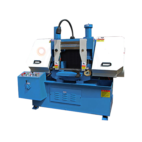
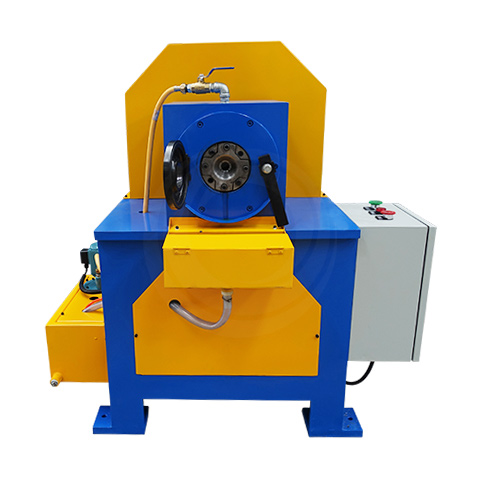
Metal Band Saw Machine
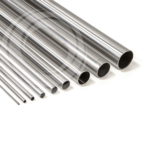
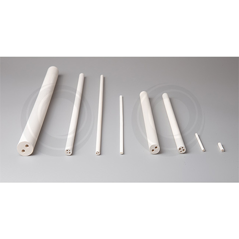
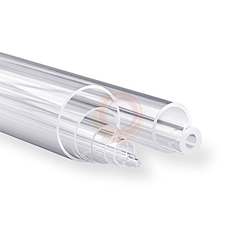
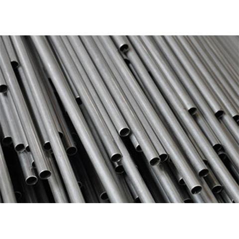
Metal band sawing machine is mainly used for sawing low alloy steel, high alloy steel, special alloy steel and stainless steel and other small and medium size bar material, tube material and plate.
Double column gantry band sawing machine series is a metal band sawing machine designed and manufactured by our company, which collects the essence of domestic and foreign products. The structure is scientific and reasonable, the appearance is generous, the cutting efficiency is high, the band saw blade has a long service life, it is the ideal cutting equipment for large and medium-sized materials. Double column gantry horizontal band sawing machine series has the features of narrow blade, material saving, energy saving, high sawing precision, easy operation and high production efficiency.
- Cutting speed is controled by hydraulic, stable sawing, high precision.
- The guide block structure is scientific and reasonable, thus extending the service life of the saw blade.
- Double column, double cylinder, gantry type is a reasonable structure and beautiful appearance.
- This machine uses two sets of front and rear vise and hydraulically tightened.
Main Modle
| Model | Unit | JQ0120 | JQ0128 | JQ0130 | JQ0135 | JQ0140 | JQ0150 | JQ0160 | JQ0165 | JQ0170 | JQ0180 | JQ01100 | JQ01120 |
| Sawing Shape | Roundness | mm | 200 | 280 | 300 | 350 | 400 | 500 | 600 | 650 | 700 | 800 | 1000 | 1200 |
| Quadrate | mm | 200x200 | 280x280 | 300x300 | 350x350 | 400x400 | 500x500 | 600x600 | 650x650 | 700x700 | 800x800 | 1000x1000 | 1200x1200 |
| Band Saw Blade Line Speed | m/min | 27、45、69 | 27、45、69 | 27、45、69 | 27、45、69 | 27、45、69 | 27、45、69 | 27、45、69 | 27、45、69 | 27、45、69 | 27、45、69 | 27、45、69 | 27、45、 69 |
| Band Saw Blade Specifications | mm | 2800*27*0. 9 | 3505*27*0.9 | 3505*27*0. 9 | 4115*34*1. 1 | 5000*41*1. 3 | 5800*41*1.3 | 6630*54*1. 6 | 7024*54*1. 6 | 7200*54*1. 6 | 8820*67*1. 6 | 9820*67*1.6 | |
| Main Motor Power | kw | 1.5 | 2.2 | 2.2 | 3 | 4 | 5.5 | 5.5 | 7.5 | 7.5 | 7.5 | 11 | |
| Hydraulic Motor Power | kw | 0.55 | 0.55 | 0.55 | 0.55 | 0.75 | 0.75 | 1.5 | 1.5 | 2.2 | 2.2 | 3.75 | |
| Cooling Pump | kw | 40 | 40 | 40 | 40 | 90 | 90 | 125 | 125 | 125 | 125 | 125 | |
| Working Clamping Mode | - | Hydraulic vise | Hydraulic vise | Hydraulic vise | Hydraulic vise | Hydraulic vise | Hydraulic vise | Hydraulic vise | Hydraulic vise | Hydraulic vise | Hydraulic vise | Hydraulic vise | Hydraulic vise |
| Main Drive Structure | - | Worm gear drive | Worm gear drive | Worm gear drive | Worm gear drive | Worm gear drive | Worm gear drive | Worm gear drive | Worm gear drive | Worm gear drive | Worm gear drive | Worm gear drive | Worm gear drive |
| Feeding Mode | - | Roller Slide | Roller Slide | Roller Slide | Roller Slide | Roller Slide | Roller Slide | Roller Slide | Roller Slide | Roller Slide | Roller Slide | Roller Slide | Hydraulic automatic |
| Weight | kg | 600 | 800 | 900 | 1000 | 1500 | 1900 | 3200 | 4000 | 5000 | 7000 | 10000 | |
| Overall Dimension | mm | 1350*900* 1200 | 1780*1050*1 500 | 1780*1050* 1500 | 1980*1110 *1600 | 2520*1200 *2000 | 2800*1300* 2100 | 3150*1350* 2200 | 3200*1380 *2200 | 3500*1600 *2400 | 3600*1800 *2400 | 4600*2000*2550/23 00*450*700 | |
| Package Size | mm | 1460*930* 1270 | 1950*1140*1 550 | 1950*1140* 1550 | 2100*1150 *1650 | 2580*1270 *2100 | 2960*1470* 2300 | 3300*1450* 2400 | 3350*1500 *2450 | 3600*1800 *2550 | 3850*2000 *2550 | 4600*2000*2550/23 00*450*700 | |
Optional Configuration
- Saw blade cover protection
- Protective cover power failure protection
- Fast down protection
- Saw blade hydraulic clamping
- Saw blade variable speed
- Hydraulic chip conveyor
- Saw blade broken protection
Structure
The main components of double-column horizontal metal band sawing machine are: bottom seat; Bed, column; Saw beam and transmission mechanism; Guide device; Workpiece clamping; Tensioning device; Feed rack; Hydraulic transmission system; Electrical control system; Lubrication and cooling system.
Hydraulic transmission system is a hydraulic circuit composed of pump, valve, cylinder, oil tank, pipeline and other components. It under electrical control to complete the lifting of the saw beam and the workpiece clamping. Through the speed regulating valve, the feed speed can be adjusted continuously to meet the needs of sawing workpieces of different materials.
The electrical control system is a control circuit composed of electrical box, control box, junction box, stroke switch and electromagnet, etc., which is used to control the rotation of the saw blade, the lifting of the saw beam and the clamping of the workpiece, etc., so that it can realize the normal cutting cycle according to a certain working procedure.
Before the lubrication system starts, it must be refueling according to the lubrication parts of the machine tool (wire brush shaft, worm gear box, active bearing seat, worm bearing, lifting cylinder upper and lower shaft, movable vice sliding surface clamping screw). The worm wheel and worm in the worm wheel box are lubricated with No. 30 oil bath, injected by the oil plug hole in the upper part of the worm wheel box. The box is equipped with oil label. When the saw beam is located at the lowest position, the oil surface should be located between the oil label and the lower limit. The oil should be changed after a month of trial, and then the oil should be changed every 3-6 months, and the lower part of the worm gear box is provided with an oil drain plug.
 Video
Video