Compensating Cable is a special cable used to extend the transmission distance of thermocouple signals. Its function is to connect thermocouples and temperature measuring instruments to ensure accurate transmission of temperature signals while reducing costs. Compensating cable is divided into Compensating cable and Extension Cable.
Compensating cable is divided into precision grade and ordinary grade according to the tolerance of thermoelectric characteristics. They are divided into general use and heat-resistant use according to the operating temperature range. According to the structural form, they are divided into single-strand core and multi-strand core.
Characteristics of Compensating Cable
The material is different from the thermocouple.
The conductor material of the compensating cable is not necessarily exactly the same as that of the thermocouple, but their thermoelectric properties within a specific temperature range (usually room temperature 0~200℃) match those of the thermocouple to ensure temperature measurement accuracy.
For example, the compensating cable of a type K thermocouple may be made of a copper-nickel alloy, rather than the nickel-chromium-nickel-silicon alloy of the thermocouple itself.
Suitable for long distance transmission, reduce costs.
Since the materials of the thermocouple (such as platinum-rhodium, nickel-chromium, etc.) are relatively expensive, using cheaper compensating cable to extend signal transmission can reduce system costs.
Suitable for short to medium distances (usually tens of meters to hundreds of meters) from thermocouples to control instruments.
Reduce measurement error.
The use of ordinary copper wire may produce additional thermoelectric potential at the contact due to different metals, affecting the measurement accuracy; The compensating cable can ensure the correct transmission of the thermocouple signal.
However, it should be noted that the compensating cable can only remain matched within its specified temperature range, outside of which may lead to increased errors.
Different thermocouple types require corresponding compensating cable.
Various thermocouples (such as K-type, J-type, T-type, S-type, etc.) have their own matching compensating cable and cannot be mixed, otherwise it will cause measurement errors.
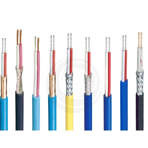
The insulation color of compensating cable is usually marked according to international standards (such as IEC, ANSI) to distinguish different types.
Thermocouple Extension Cable vs. Compensating Cable
Item
Compensating Cable
Extension Cable
Conductor material
Inexpensive material that is different in composition from the thermocouple but matches
Same material as thermocouple composition
Applicable temperature
0~200°C(General environment)
Suitable for higher temperatures
Measurement accuracy
Slightly lower accuracy, but sufficient for industrial applications
Higher accuracy for precise measurements
Application scenarios
Long-distance signal transmission, reducing costs
For high-precision measurement is required
If your thermocouple signal requires higher accuracy and longer distance transmission, it is recommended to choose a suitable thermocouple extension cable to ensure measurement accuracy and system stability!
P: Shielded type (tinned copper wire or galvanized steel wire or aluminum-plastic composite tape)
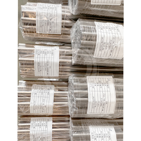
Product specification:
Logarithm times*cross-sectional area
Compensating Cable Use Precautions
Correctly match the thermocouple model. Different types of thermocouples require corresponding compensating cable.
Avoid over-temperature use. Compensating cable can usually only maintain accurate matching within the range of 0~200℃. Too high a temperature will cause errors.
To reduce electromagnetic interference, shielded compensating cable can be used for long-distance transmission to reduce the impact of external electromagnetic interference on the signal.
The connection method is correct, and the positive and negative poles of the thermocouple and the compensating cable must be connected correctly, otherwise it will cause temperature measurement errors.
Customers who bought this product also bought
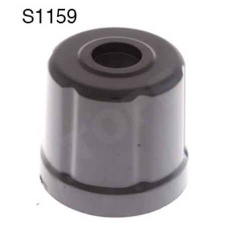
Caps For Heaters S1159
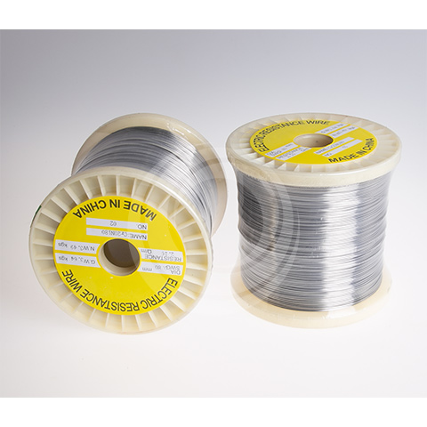
Resistance Wire Nickel Chromium
Resistance Wire Nickel Chromium
Ceramic Terminal Block S0077
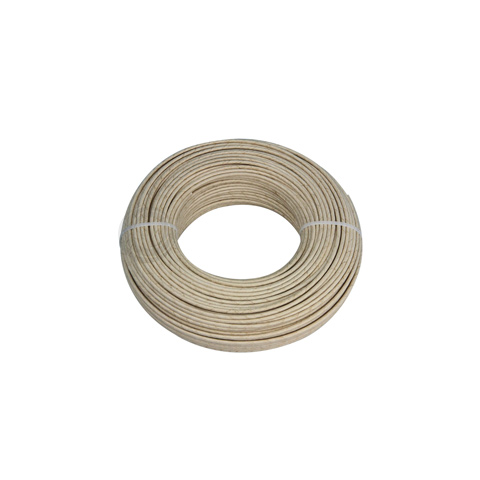
Compensation Cable For Resistance Thermometers Rtd
High Temperature Fire Resistant Cable
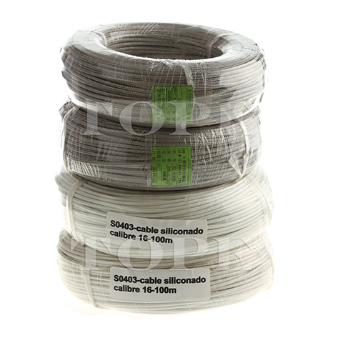
High Temperature Silicone Cables
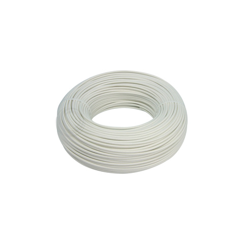
Compensation Wire For Thermocouple
High Temperature Silicone Cables
Cap S1159
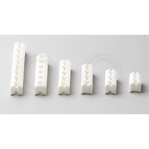
Ceramics For Band Heater
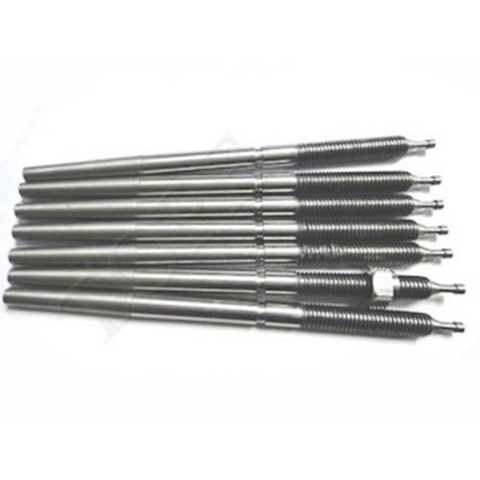
Magnesia Rod 480
Ceramic 42
Resistance Strip High Temperature
Ceramica 14
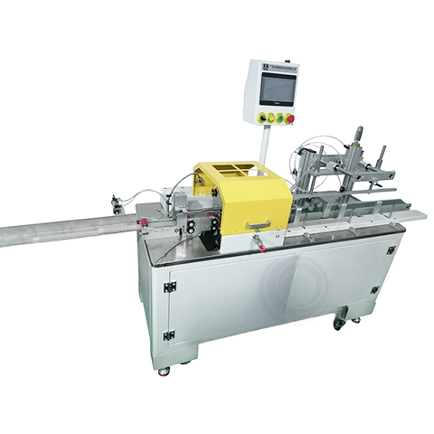
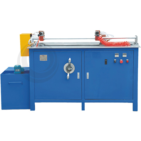
Wire Decoiling Straightening And Cutting Machine XZ04
High Temperature Plug S0017
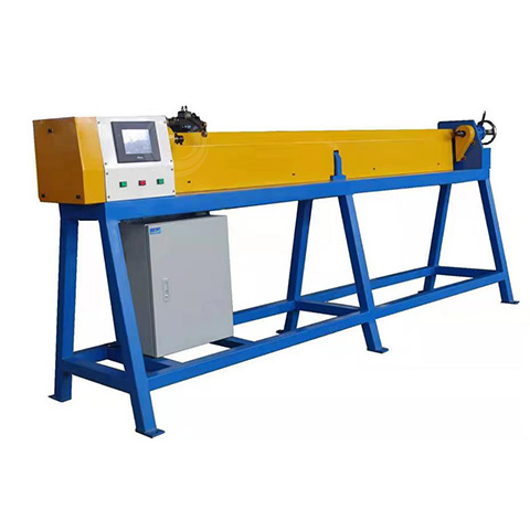
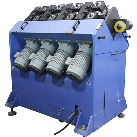
Straightener For Pipe And Rod Of Brass And Aluminum
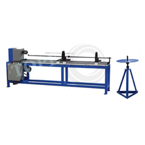
Straightening Machine XZ01-3
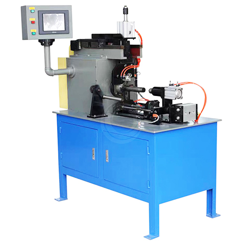
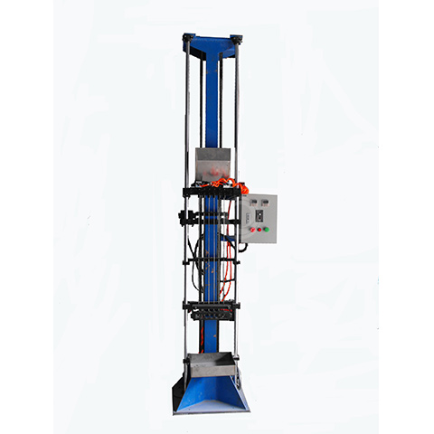
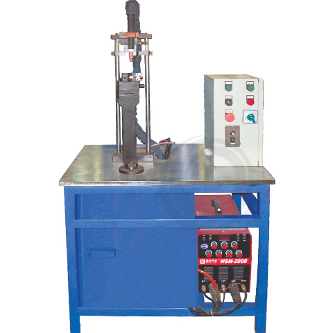
Automatic Testing Machine For Heating Elements 2
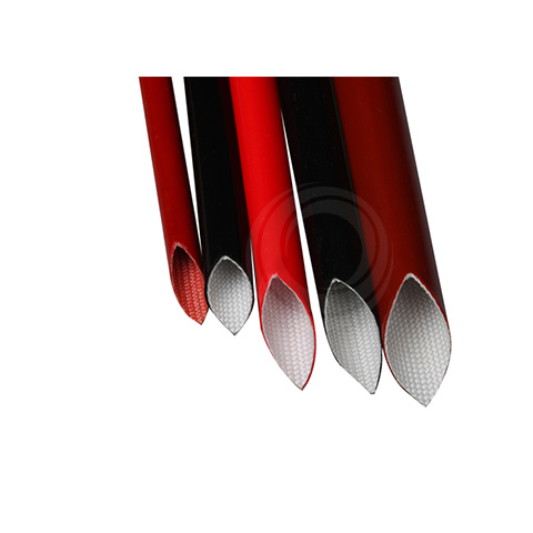
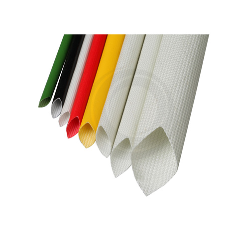
Sleeving Fibra De Vidrio Dentro Y Silicona Fuera
Flange For Heating Elements
Silicone Resin Coated Fiberglass Sleeving
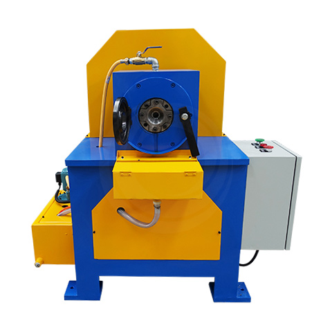
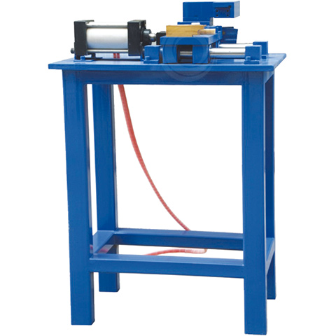
Swaging Machine DGSG01
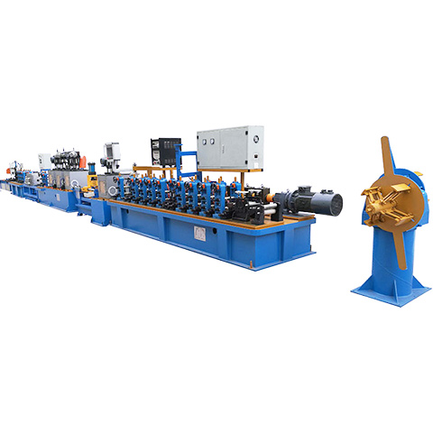
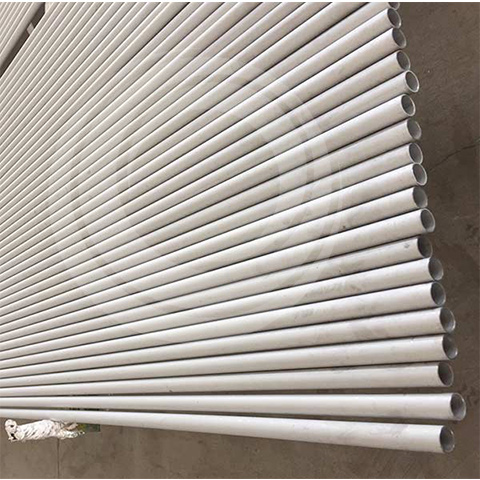
Stainless Steel Tube Making Machine
Filling Machine For Tubular Heater TF02
Filling Machine For Cartridge Heater DGTF01
Magnesium Oxide Insulator
Wire Winding Machine RX01
Mgo Rod Coiling Machine DGRX01
Mica Coiling Machine Automatic Feeding
Wire Coiling Machine For Hot Runner Heater
Winding Machine For Fin Heater RP01
Bending Machine For Hot Runner Heater RDWG01
U shape Hydraulic Bending Machine WG02-Y
Rolling Mill Improve The Accuracy
Edge Rolling Machine For Band Heater
Swaging Machine for Hot Runner Heater RDSG01
Three Guide Tube Filling Machine | Latest |For Long Tube