How to make heating elements? - The Production Process of Electric Heater
Author:Judy Peng TOPE INT’L CO., LIMITED
©All Rights Reserved. The contents of this document cannot be reproduced without prior permission of the authors.
Summary:How to make electric Heaters? This article is talking about the basic production process of electric heater. To make a good quality of electric heater, there are many factors, we can’t specify all the details here. But we are trying to include all the complete process here.
Keyword: production process of electric heater, Machines used for electric heaters, Raw Materials you may need for electric heaters .
Many people have been extremely curious to know how tubular heaters are manufactured. The following section comprises of the actual record of detailing the procedures of producing tubular heaters.
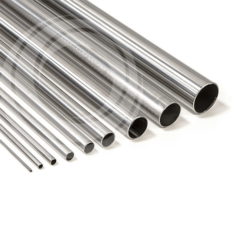
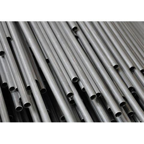
1. Cutting of tubes (Material preparation)
- a. Measure the dimensions of the tubes. It is mainly to ensure that the standard deviation of the outer diameter of the tubes is within ≤0.2mm; while the standard deviation of the thickness of the tubes is within ≤0.2mm.
- b. The end cut must not have any burr, that arises from the friction between the cutting blade and the cut-out surface.
- c. The width of the end cut must not be more than 2.5mm.
- d. The length tolerance is within ±0.5mm.
- e. It is mainly self-checking. The inspector will check first, and he will subsequently conduct sample testing.
Measuring tools and equipment: Stainless steel tube cutting blade, steel ruler, measuring tape, caliper, Tube Cutting Machine .
2. Chamfering (Removal of burrs)
- a. Place the two ends of the internal holes of the tubes at a chamfer of 0.3×45°. There must not be any burr. Compress the tubes with 6 – 7 kilograms’ force of compressed air pressure, and immerse the tubes into a water tank to check whether there is any air bubble.
Measuring tools and equipment: Drilling bit, trolley, air compressor, water tank, external pressure gauge, deburring machine .
3. Cleaning of tubes
- a. Use a brush to clean the tubes to-and-fro for two consecutive times. If the internal tube walls are too dirty, use the steel wire balls to brush clean and remove any residues with compressed air. Under the sunlight, observe the conditions within the tube walls.
Measuring tools and equipment: Long-handle brush of various specifications, stainless steel wire ball.
4. Pushing plastic plug
- a. Push the terminal pin into the plastic plug. The pushing dimension will be determined by the length in which the terminal pin is inserted into the tube under the production specifications.
Measuring tools and equipment: Steel ruler, hand press, plug and pin assembling machine
5. Coiling
- a. According to production specifications, select the types of wires , diameters of wires and the core mandrel. Note: Check the diameters of wires.
- b. Ensure the coiling distance is uniform and there must not be any phenomenon of “coil-jumping.”
- c. Insert the terminal pin . According to production specifications, ensure the coiling resistance. Check the actual length of dense coiling. If the actual length of dense coiling is within ±10mm as compared to the length of dense coiling specified in the production specifications, it will be passed.
- d. It is mainly self-checking. The inspector will conduct sample testing.
Measuring tools and equipment: Coiling Machine , coiling mandrels of various specifications, measuring tape, digital resistance meter.
6. Spot welding (Oxy-fuel welding)
- a. Ensure the terminal pin and the Resistance Wire to be tightly in-contact after the insertion.
- b. Make sure the welding is firm and robust and ensure that the resistance wire will not decouple from the terminal pin during the tube rolling.
- c. Adjust the welding current to the point at which the spot welding torch emits smoke without lighting it. This is the best welding current. The spot welding must be executed 2mm and above away from the end surface of the wiring portion of the terminal pin. There must not be less than 2 spot welding locations. Particularly spot weld on the first round of wiring head and make sure that the wiring head must not bulge.
- d. For wire diameter greater than 0.8mm, oxy-fuel welding must be used. The spot welding must be located at the ending portion of the space between the first and second round of the Resistance Wires. The rest that are closer to the flame must be wrapped with wet asbestos to prevent the gradual annealing of the wires causing the phenomenon of uneven wire-pulling.
- e. When moving the finished products, they must be carefully lifted and placed ensuring that the resistance wire will not deform.
- f. After passing the QC, the finished products will continue to the next procedure.
Measuring tools and equipment: Energy-saving Welding Machine , oxy-fuel welding equipment, welding rod.
7. Filling (Critical procedure)
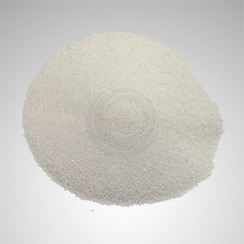
- a. Use high-grade gasoline to clean the wires and dry them with compressed air.
- b. Spread the Magnesium Oxide Powder(Mgo powder) on the tray and the thickness must not be more than 40mm. Place them in the oven. When magnesium core is needed, place the magnesium core into the oven too. Bake them for 1 to 3 hours under the temperature of 100℃ until they are completely dry. The best is to add the powder with temperature.
- c. According to production specifications, ensure the length of the terminal pin after inserting it into the tube.
- d. When the wire diameter ≥0.5mm, the allowance given to wire-pulling must be equivalent to two-thirds of the tube length. For magnesium core, it must be lightly pulled.
- e. After filling the powder , the required filling proportion must reach 2.4~2.6g/cm 2.
- f. The principle of vibration frequency adjustment: The slimmer the resistance wire, the smaller the vibration during vibration adjustment. Note: The phenomenon of “wire sagging” will occur.
- g. The hollow plug must ensure it will not cause the terminal pin to move and rotate. At the same time, it must also make sure that the plug is firmly compressed and the powder will not leak.
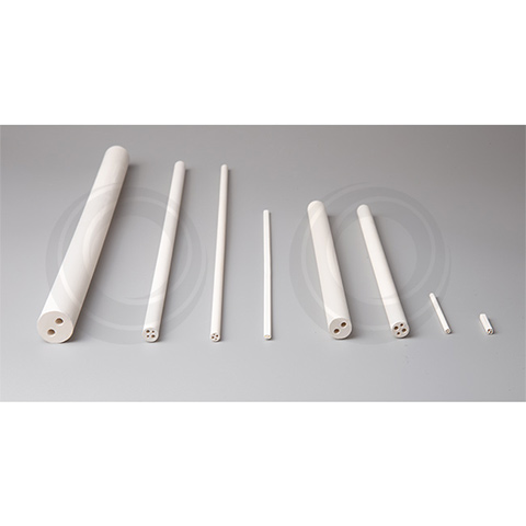
- h. When choosing the guiding tube (The guiding tube has two layers. It is formed with two tubes bonded together. While the inner tube is called the internal guiding tube, the outer tube is called the exterior guiding tube.), the outer diameter of the guiding tube must be smaller than the inner diameter of the element tube by less than 0.5mm; and the inner diameter of the inner guiding tube must not be larger than the maximum outer diameter of the wire by less than 0.5mm.
- i. Conduct self-checking on the withstanding voltage and insulation. After passing the QC, the finished products will continue to the next procedure.
- j. Precautions on the addition of powder (Technique and process description)
- 1. Visually inspect the uniformity of the spiral resistance wire . That is, to pull the resistance wire to half of the tube length. Observe whether the density is basically uniform.
- 2. Verify the material of the terminal pin, the length and diameter. If there is any crooked bend, it must be instantly rectified.
- 3. If the tube is bent, it must be instantly rectified.
- 4. The formula for calculating the weight of the powder added (ignore the wire weight, terminal pin and plug weights):
W=d2·L·V≈0.785 d2·L·V
where d - Internal diameter of tube (cm)
L – Length of tube (cm)
V – Density of powder, 2.4~2.6g/㎝2
Measuring tools and equipment: Powder Filling Machine , automatic disintegrator, oven, measuring tape, cleaning tray, gasoline.
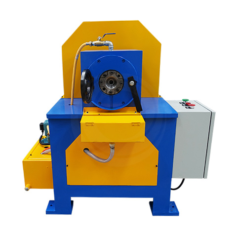
8. Tube rolling
- a. Clean thoroughly all areas of the tube.
- b. Pay extra attention to the direction and ensure that the plastic plug enters the reduction Rolling Mill first. (Air heating tubular heaters support the phenomenon whereby the air heating tubes will first be inserted into the tube rolling mill at one end for the first round of tube rolling, and thereafter, the other end will first be inserted into the machine for the second round of tube rolling.)
- c. After tube rolling, the standard deviation of the tube diameter is within ±0.08mm, including the standard deviation of round deviation).
- d. After tube rolling, the linearity must not be greater than 4mm per meter.
- e. In each adjustment of the Roller, the testing sample must not be more than 8 pieces.
- f. The inspector will conduct sample testing for the diameter and linearity of the tubes. Additionally, a sample testing of 20% of the resistance values and the tube lengths will also be taken.
Note: After tube rolling, the difference between the longest and the shortest tube must not be greater than 3%. If the disparity is excessively large such that it cannot be rectified, the wasted product will be calculated to the procedure of powder filling.Measuring tools and equipment: Tube rolling mill , measuring tape, caliper.
9. Lathing the two ends
- a. Ensure that the Terminal Pins are symmetrical after the lathing operation. The difference between the outer lengths of the two ends must not be greater than 2mm.
- b. The standard deviation of the tube lengths must be within ±0.5mm.
- c. Use a file to remove the burrs at tube ends.
- d. It is mainly self-checking. The inspector will conduct sample testing.
Measuring tools and equipment: Lathe gauge, stainless steel blade, measuring tape, steel ruler, trim machines
10. Annealing
- a. Whether to anneal the tubes, the annealing methods as well as the temperature will all depend on the requirements in the production specifications.
- b. When the electric furnace is annealing, place the tubes uniformly in different layers in the furnace. There must not be any congestion that causes uneven annealing.
Measuring tools and equipment: Annealing furnace , partial Annealing Machine , oxy-fuel welding equipment.
11. Tube bending
- a. According to the production specifications, cut the length of the exposed terminal pin. Grind away the broken threads at the end of terminal pin and chamfer it at 0.5×45°. Ensure that the threads can successfully screw in.
- b. Based on the picture or sample, bend the tubes into the required shapes. The exterior of the tubes must not have apparent machinery scratches or partial expansion. The bending point must also not be wrinkled and uneven.
- c. In the situation that the bending radius is less than 3 times of the tube diameter and without annealing, make sure that the direction of the welding joints is pointing towards the inner R (not easily broken).
- d. It is mainly self-checking. The inspector will check first, and he will subsequently conduct sample testing.
Measuring tools and equipment: Tube-bending tool, Bending Machine , hydraulic press, punching machine, caliper, universal angle ruler, measuring tape.
12. Welding
- a. For soldering of Flanges or rapid welding of various plates, the soldered items must be firm and reliable.
- b. Used in heating fluids or sealing components, it must withstand the pressure of 0.3~1.2MPa. After several hours of 5mm of hydrostatic test, there must not be any leakage.
Measuring tools and equipment: Oxy-fuel welding equipment, various welding rods.
13. Sealing
- a. Sealing is conducted according to the production specifications.
- b. Dig out the MgO powder with a depth of 3 to 4mm from two sides of the element tube and clean thoroughly. Take extra precaution to note that there must not be any magnesium powder on part of the screw threads and the inner wall of the tube.
- c. Prior to sealing, check that the components can withstand the voltage of 2000V/1s without any disintegrating arc-over and infinite insulation.
- d. Drip the sealing glue , rotate and compress the ceramic plug . Then secure with the screw nuts and washers.
- e. The two-time sealing of the heating components shall be implemented according to the operating procedures.
14. Surface treatment
- a. According to the production specifications, it will decide on whether the surface must be treated as well as the types of surface treatment.
- b. The composite surface layers must be painted uniformly and with shine. There must not be any bubbles, peeling and piling phenomenon.
- c. During acidic cleaning, the terminal pin must not be damaged or corroded.
- d. Treat and clean the surface in advance, particularly the glue, oxidized spots, etc.
15. Final testing
- a. Insulation: Infinite, time duration of 10s.
- b. Withstanding voltage:
For φ16 and above and the length is within 4m - 3000V/10s.
For φ8 to φ10 and the length is within 4m - 2000V/10s.
For φ6.5 and the length is within 2m - 1800V/10s.
No phenomenon of disintegrating arc-over.
- c. Cold resistance: Comply with the requirements of production specifications.
- d. Exterior checking. The geometrical shape and the dimensions must comply with the product requirements.
- e. For leakage of currents, each sampling testing is 5%; the leakage of currents is less than 0.5mA.
- f. For hot insulation, each sampling testing is 5%; at the same time, observe the uniformity of heat.
When the current is cut off, check that the hot insulation is ≥2MΩ within 1 minute. Under the natural conditions, monitor the insulation after cooling for 1 hour. The insulation shall restore to 100 MΩ and above.
Measuring tools and equipment: Automatic disintegrator, digital resistance meter, current leakage meter, caliper, measuring tape, steel ruler, flat panel, Testing Machine .
16. Marking and Packaging
According to customers’ requirements.